Things To Remember When Installing Ceiling Fans Installation

Ceiling Fan Installation and Usage Tips

Ceiling fan performance and energy savings rely heavily on the proper installation and use of the ceiling fan. Here are a few tips to ensure quality and product performance.

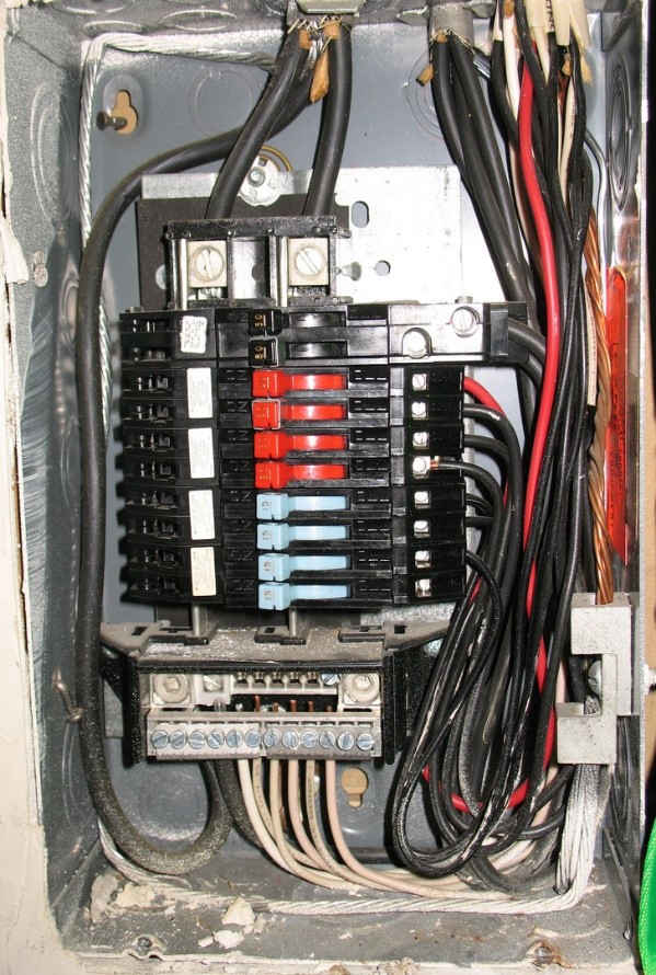
Choosing the Appropriate UL-Rated Electrical Box

Make sure that you use the appropriate UL-listed metal box, marked “For Use With Ceiling Fans.” This outlet box is mounted above the ceiling and also is the point where the fan is attached. This box houses all wiring needed to operate and connect the ceiling fan. If you are replacing a ceiling fixture, most likely you will need to replace the electrical box.

Mounting the Ceiling Fan

If possible, the ceiling fan should be anchored to a ceiling joist. In the case that the joist is not located in the center of the room, a special ceiling fan mounting bracket with spiked ends should be installed between joists. Keep in mind that ceiling fans can weigh as much as 50 pounds!

Balancing a Wobbly Fan

All fan blades should be balanced prior to shipment; however, if the fan is wobbly after installation, there are ways to fix it. First, make sure that all connections are properly aligned and tightly fastened. Check the alignment of the blades by holding a yardstick vertically along the edges; you may be able to gently bend a misaligned blade holder back into proper place. If all blades are aligned, a balancing kit can then be used to pinpoint the culprit. These kits are either provided within product packaging (e.g., balancing clips and blade weights) or can be sent by the manufacturer free of charge. View(link is external) a video with tips on fixing a wobbly fan.

Turn Off When not in the Room

Ceiling fans cool people, not rooms. If the room is unoccupied, turn off the ceiling fan to save energy.

How to Install a Ceiling Fan

Installing a ceiling fan is a good project for the do-it-yourselfer, as you can simply replace a traditional lighting fixture with a fan or fan-and-light kit. You can wire the fan’s light to be controlled by the light switch on the wall and allow the fan to be turned on manually by pulling a cord, install a second switch to control the fan, or purchase a unit operated by remote control.

You’ll need to ensure that the junction box to which you will connect your fan can support its weight (it should say “suitable for fan support”), that you have enough clearance between the fan blades and the ground (at least 7 feet), and that your fan is the appropriate size for your room. For more, see Sizing & Locating a Ceiling Fan.

Remove the old light fixture. (See How to Replace a Light Fixture for information about how to do so.)

Install a ceiling fan mounting bar. If the ceiling box is connected at its center to a bar hanger attached to two joists

If it is not, you will have to install a ceiling fan box with a mounting bar. Take out the old ceiling box, and insert the hanger bar for the mounting box into the ceiling hole. Ram the edges (or “feet”) of the bar toward the two ceiling joists by turning the center of the bar, and use a wrench to tighten the bar and embed the sides into the joists. Attach the ceiling box to the hanger.

Ceiling Fan Frequently Asked Questions

When it comes to ceiling fans I find my clients have a lot of questions, and are unsure about the many types of ceiling fans, installation techniques and what it all means for them. Here I have compiled FAQ’s that I get asked often, as well as some information that you will find informative.

How much do ceiling fans cost to run? A Ceiling Fan is cheap to run at about 2-3 cents per hour. Here’s a great link for calculating any appliance costs in Adelaide Calculate Appliance Running Costs. A Ceiling Fan will also aid in saving cooling costs when used in conjunction with home air conditioners.

What does the Summer/Winter switch do? This switch is found above the motor on the ceiling fan and sometimes labelled S and W. In the Summer position, the fan will blow cooling air down that you can feel. In the Winter position, the fan will turn in reverse. This blows warm air over the ceiling and down the walls.

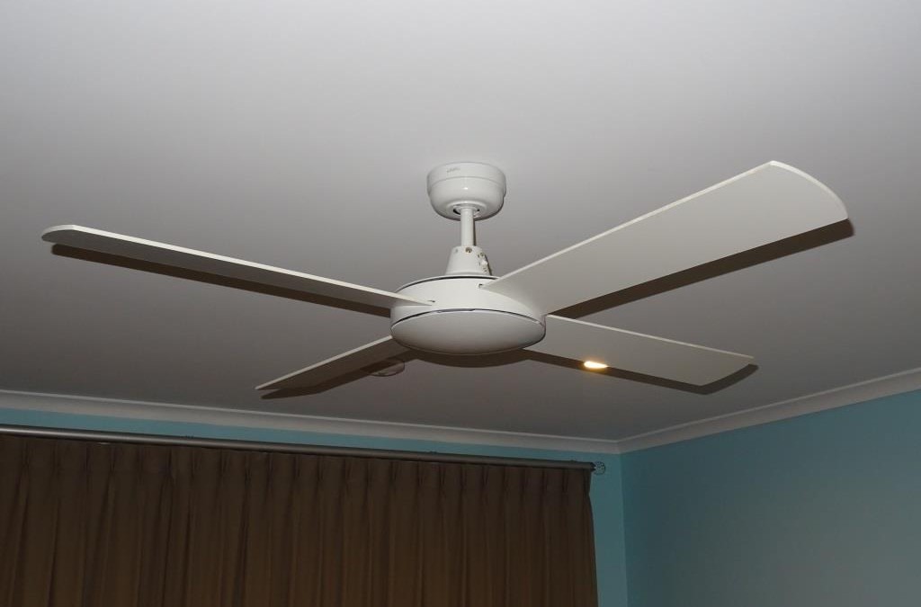
What does the number of blades mean? The most common are 3, 4 or 5 blade fans. There’s not a lot of difference in air flow. A 5 blade fan has more drag and will require more power to run the fan. A 3 blade fan is usually a metal blade fan designed to push a lot of air for its size and thus can be a little noisy. A 4 blade fan tends to be a good compromise for air flow and efficiency. Very large fans may have more blades due to design and aesthetics.

Metal or Timber Blade Fan? A metal blade fan in most cases will push more air than a timber blade fan due to the blade angle and design. As a result they are a little noisier but work well in living areas and outside areas. A timber blade fan is quieter to run and well suited to sleeping areas, however they do not push as much air as a metal blade fan.

WHICH WAY SHOULD YOUR CEILING FAN SPIN AND OTHER HELPFUL COOLING TIPS

Summer is coming, and we can feel the sweat and see the high electric bills already! One way to lower the cost of running your air conditioning unit is also to use your ceiling fan. Ceiling fans circulate cooled air in a room to make people feel cooler. That means you can increase your thermostat by several degrees without causing a noticeable difference in comfort.

Many people don’t realize that you can save money in the summer by running your ceiling fan in conjunction with your air conditioner. With a ceiling fan running, you can feel about 5 degrees cooler. This means you can turn down your AC and lessen its running load. Before you turn your AC on in the shoulder seasons, try running your fan first and see if you can save even more money by avoiding AC for a couple more weeks or most waking hours. A typical central air conditioning unit uses about 3,500 watts of energy when running, while an average ceiling fan running on high uses only about 60 watts.

Which Direction Should Your Ceiling Fan Spin in Summer?

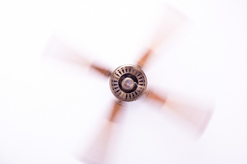
Most fans have a clockwise and counterclockwise setting, usually controlled by a small button or switch near the fan base. Each direction is appropriate for different seasons. However, because fan blades are also angled, we cannot tell you which direction works for which season, on your specific fan. You’ll have to do a small experiment.

Stand beneath your fan and turn it on. If you immediately feel a breeze, that is the summer setting. If you do not immediately feel a breeze, turn off the fan, and look for the small button to run the fan in the opposite direction. Take this opportunity to dust your fan. It’s often an overlooked task, but removing any particulates from the air in your home helps keep the air quality high while also cutting down on internal cleaning of the air ducts.

Ceiling Fans Keep People Cool, Not Rooms

What do we mean? Unlike a central AC unit that is cooling your home, a fan is creating a cooling effect. Fans will not lower the temperature; they make you feel cooler by circulating the air. A fan is like a gentle breeze, but if you think about it, your furniture doesn’t benefit from that feeling, only you do. That means when you leave a room, turn off the fan to save on your electric bill.

Helpful Tips For Purchasing A Ceiling Fan

That thing hanging from the ceiling that provides a cool breeze is an often overlooked part of most rooms of a house. However, if used correctly it can shave some serious dollars off of your energy bill each month, especially during the spring and summer months. So, when it’s time to purchase a new ceiling fan, we highly recommend spending a bit of time doing some research and finding one that checks off all of the following considerations

Airflow

This may sound obvious, but a ceiling fan that really provides adequate airflow and circulation is a must. What you may not know however, is that a ceiling fan’s airflow is measured in cubic feet per minute and the fan’s maximum airflow will be listed on the box.
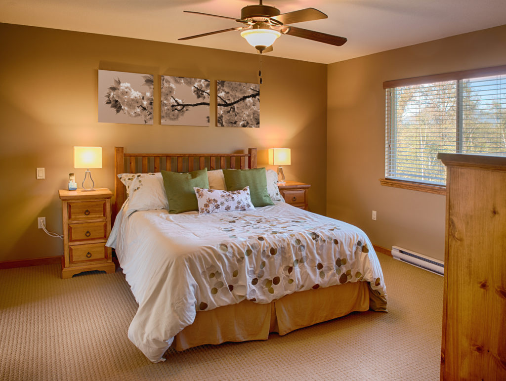
Light Combos

Lots of ceiling fans on the market today incorporate some sort of lighting, if that’s something you prefer. While shopping, it’s important to think about the room the ceiling fan will be installed in and determine whether or not you need some extra overhead lighting.

Efficiency

As we mentioned above, a ceiling fan can really help you save on energy bills if you use it correctly, especially if you use it in conjunction with your air conditioning system. With that said, you’ll want to make sure you’re looking at ceiling fans that are Energy Star rated if it comes with a lighting kit, so be on the lookout for the little blue label.

Location

Did you know there are three main types of fans when it comes to the location where it will be installed? If you’re going to be installing the fan outside, you’ll want to look for one that is wet-rated as opposed to a dry-rated fan if it will only be used indoors. If it’s going to be installed somewhere in between or a room of the house with high humidity (like the bathroom or the laundry room), your best best is a damp-rated ceiling fan.

Types Of Electrical Wiring For Different Wiring Applications

Electrical Safety: Safety & Health for Electrical Trades

How Do You Control Hazards?

In order to control hazards, you must first create a safe work environment, then work in a safe manner. Generally, it is best to remove the hazards altogether and create an environment that is truly safe.

How Do You Create a Safe Work Environment?

A safe work environment is created by controlling contact with electrical voltages and the currents they can cause. Electrical currents need to be controlled so they do not pass through the body. In addition to preventing shocks, a safe work environment reduces the chance of fires, burns, and falls. You need to guard against contact with electrical voltages and control electrical currents in order to create a safe work environment

Make your environment safer by doing the following:

Treat all conductors—even “de-energized” ones—as if they are energized until they are locked out and tagged.

Lock out and tag out circuits and machines.

Prevent overloaded wiring by using the right size and type of wire.

Prevent exposure to live electrical parts by isolating them.

Prevent exposure to live wires and parts by using insulation.

Prevent shocking currents from electrical systems and tools by grounding them.

Prevent too much current in circuits by using overcurrent protection devices.

Lock out and tag out circuits and equipment

Create a safe work environment by locking out and tagging out circuits and machines. Before working on a circuit, you must turn off the power supply. Once the circuit has been shut off and de-energized, lock out the switchgear to the circuit so the power cannot be turned back on inadvertently. Then, tag out the circuit with an easy-to-see sign or label that lets everyone know that you are working on the circuit. If you are working on or near machinery, you must lock out and tag out the machinery to prevent startup. Before you begin work, you must test the circuit to make sure it is de-energized.

Lock-Out/Tag-Out Checklist

Lock-out/tag-out is an essential safety procedure that protects workers from injury while working on or near electrical circuits and equipment. Lock-out involves applying a physical lock to the power source(s) of circuits and equipment after they have been shut off and de-energized. The source is then tagged out with an easy-to-read tag that alerts other workers in the area that a lock has been applied.

Electrical Wire Size Required for Receptacles

What size electrical wire should you use when hooking up an electrical receptacle (wall plug or electrical outlet)? Here we explain the choice of No. 14 or No. 12 copper wire for 15A and 20A electrical circuits where receptacles are being wired.

This article series describes how to choose, locate, and wire an electrical receptacle in a home. Electrical receptacles (also called electrical outlets or “plugs” or “sockets”) are simple devices that are easy to install, but there are details to get right if you want to be safe.

What Size Electrical Wire Should I Use When Wiring an Electrical Outlet (Receptacle)?

The electrical wire used for the receptacle circuit must be the proper type in size (thickness or gauge) and number of conductors for the ampacity of the electrical circuit

The electrical circuit must be properly protected by the right fuse or circuit breaker

For a 15-Amp circuit use #14 copper wire (or #12 copper-clad aluminum wire). The fuse or circuit breaker feeding this circuit is rated for 15 amps.

For a 20-Amp circuit use #12 copper wire (or #10 copper-clad aluminum wire).The fuse or circuit breaker feeding this circuit is rated for 20 amps.

For a 30-Amp circuit use #10 copper wire and a fuse or circuit breaker rated for 30 Amps.

For other wire sizes and a complete wire size table see SE CABLE SIZES vs AMPS – separate article

Note1: it’s safe and OK to use a smaller (lower ampacity) fuse or circuit breaker, such as a 15-amp fuse protecting a circuit wired with #12 copper wire

Note2: it’s generally safe and OK to use a larger size electrical wire, and a larger wire size may in fact be required for longer wiring runs. Generally you want a 3% or less voltage drop across the wire from source to point of use. For the U.S., electrical wire sizes vs. circuit ampacity are given in National Electric Code Table 310-16

All You Need To Know About Electric Wiring and Rewiring

Electric wiring and rewiring is an important aspect of consideration when you are renovating your old home or building a new one. It is a complex and time-consuming process which ideally should be done by trained professionals. When you make the decision of wiring or rewiring your home or office, you can come across a number of choices to make.

You can select from the different types of wiring materials which are available and the different wiring installation processes. Here, we will discuss some of the most common aspects of wiring/rewiring starting from the signs through which you can tell whether rewiring is required or not along with the different types of electrical wirings and their corresponding installation processes.

Signs That Your House or Office Needs Rewiring

Before the electrical system in your house or office collapses or causes any serious problems because of bad wiring, there are certain signs for which you can look out to determine if the electrical wiring needs to be repaired or replaced.

These signs are listed below:

Damaged or frayed wires are the first thing that you should keep a look-out for. This kind of damage may be caused by rodents, heat, corrosion, or simply because of being old. The frayed wires can not only lead to further electrical problems like short circuiting but can also pose a serious threat of electrocution.

If your electrical switches or plugs become warm or hot during usage, it can indicate a problem with the wiring. Improper wiring can cause overheating and result in serious electrical problems.

If your circuit breaker keep tripping, it can also indicate a problem with the wiring of the house.

If you notice smoke coming out from any power socket or an electrical appliance, it can be due to faulty wiring of the house.

If you notice that some of your lights flicker or dim when certain high-power appliances are plugged in, this can also indicate a problem with the wiring. The wiring may not be able to handle the load of the high-power device resulting in flickering or dimming of lights.

If you notice any loose connections near the power sockets, switches, and wires, try tightening them to not let the wiring get damaged any further.

Different Types of Electrical Wirings

When you want to change the wiring of your home, you will have the choice of selecting from several kinds of wirings available

Non-Metallic Cables (NM Cables)

NM cables are the most common types of wires which are used in houses and residential buildings. They contain three types of wires distinguished by different colors.

Electricians

Finding a home electrician

Most homeowners call electricians in an emergency or if they’re building or remodeling. It’s important to research a contractor and find a skilled electrician before you need one. By building a rapport with an electrician, you can be sure that they will be there to help when you need their services. So, you’ll want to hire an electrician for regular inspections before an emergency takes place. A good electrical contractor will become familiar with your home’s systems and possibly discover emerging problems before they become major situations.

Hiring an electrician is an important decision because they work with critical home systems that affect nearly every aspect of the building and can cause significant inconvenience, damage or even house fires if the work goes wrong.

Up-to-date education: A reputable company will require staff to attend regular training courses and stay current on the National Electrical Code, which is amended every three years.

Pulling permits: A permit is usually required in most counties and from the power company any time you’re replacing a home’s main electrical equipment or doing a significant amount of rewiring. The cost of the permit is often included in your electrician’s bill, but be sure to ask. With the permit comes an inspection to ensure the work meets code.

Legitimate licensing: If your state requires electricians to be licensed, check that the license is current. Poor wire connections, overloaded circuits, improper grounding and broken safety elements on an electrical panel are just a few of the problems that can arise from bad workmanship. To check an electrician’s licensing. You should also protect yourself by verifying the hold the appropriate bonding and insurance, including general liability and workers’ compensation coverage.

Electrical Rough-in Tips

Whether your project is finishing a garage or a basement or building an addition, it’s important to get the rough-in wiring done right the first time. We talked with several pros and got advice on drilling holes, installing boxes and pulling cable. With these tips in hand, you’ll work faster, avoid disasters down the road and put a smile on the face of your electrical inspector.

Which electrical box works best?

Either plastic or fiberglass boxes will do the job, and each is completely code compliant. Some electricians prefer fiberglass models because they’re tougher, but others prefer the plastic models because they’re cheaper.

Special cable staples

Staples (and drilled holes) need to be at least 1-1/4 in. away from the edge of a framing member. In some cases, that means stacking wires on top of one another and using one staple to secure them. Most standard staples can handle two wires. Never install staples over multiple wires unless the staple is approved for it. The staple package should list how many wires it’s rated for. The staple shown here is good for up to four wires.

Auger nits and angle drills work best

A 3/4-in. spade bit will work OK for drilling the holes, but auger bits drill faster and require less effort. Choose a bit like this Milwaukee ship auger bit that will chew through nails. It’s easier to drill straight holes through the studs with a right-angle drill. You can rent right-angle drills by the day, or you could buy an angle attachment for your own drill.

Install plates before pulling wire

Electrical cables need to be set back 1-1/4 in. or more from the edge of a stud or wood-framing member to protect cables from wayward nails and screws. Install steel cable-protection plates over holes drilled closer to the edge. Keep several plates in your pouch while you’re drilling and install them right away so you don’t forget.

Circuit Breakers In Your Home

A GUIDE TO TROUBLESHOOTING CIRCUIT BREAKERS

An electric circuit breaker is an important part of any electrical wiring system. It is designed to interrupt the flow of electricity the moment a fault, such as an overload or short circuit, occurs. Circuit breakers are made in a variety of sizes, depending on the area they cover. As a homeowner, it is important to know about some common electric circuit breaker problems and their solutions.

CIRCUIT OVERLOAD

A circuit can become overloaded when more current (amps) runs through the circuit than it was designed to handle safely. Overloads can be caused by operating too many devices on one circuit, a malfunctioning appliance or by loose or corroded wires or connections.

Circuit breakers come in different amperage ratings that determine how much current can safely flow through the circuit. If a 15 Amp circuit breaker is protecting a series of receptacles with various devices plugged in, like a hair dryer, computer and television, the circuit breaker will trip if the current exceeds 15 Amps. This prevents overheating, which can cause a fire. In the case of a breaker trip where overload is suspected, unplug all the items on the circuit before resetting the breaker.  After it is reset, turn on the devices, one at a time, to determine what may have caused the overload.  If a circuit overload happens on a regular basis, a new dedicated circuit may need to be installed to handle the amperage load.

The Basics of Electrical Testing

Electrical testing in its most basic form is the act of applying a voltage or current to a circuit and comparing the measured value to an expected result. Electrical test equipment verifies the math behind a circuit and each piece of test equipment is designed for a specific application.

It is the job of a test technician to know which piece of test equipment to use for the task at hand and also understand the limitations of the test equipment they are using. In this article, we take a look at the most common pieces of test equipment used in the field.

Multimeter

Also known as a VOM (Volt-Ohm meter), a multi-meter is a handheld device that combines several measurement functions (such as voltage, current, resistance and frequency) into a single unit.

Multi-meters are mainly used to troubleshoot electrical problems in a wide array of industrial and household devices such as electronic equipment, motor controls, domestic appliances, power supplies, and wiring systems.

Digital multi-meters are the most common form of meter used today; however analog multi-meters are still preferable in some cases, like when monitoring a rapidly changing value or sensitive measurements, like testing for CT polarity.

Megohmmeter

Most commonly referred to as simply a “megger”, a megohmmeter is a special type of ohmmeter used to measure the electrical resistance of insulators.

Resistances values by megohmmeters may range from several megohms to several million megohms (teraohms). Megohmmeters produce high voltages via battery powered internal circuitry or a manually operated generator with outputs ranging from 250 to 15,000 volts.

Megohmmeters are one of the most frequently used pieces of test equipment and can be used to measure the insulation of various types of apparatus such as circuit breakers, transformers, switchgear and cables.

Low-Resistance Ohmmeter

Often called a DLRO in the field, the low-resistance ohmmeter is used for making high-precision resistance measurements below 1 ohm. Low-Resistance ohmmeters produce low voltage DC currents via battery power with outputs of up to 100A.

Resistance measurements are achieved with four terminals, called Kelvin contacts. Two terminals carry the current from the meter (C1, C2), while the other two allow the meter to measure the voltage across the resistor (P1, P2). With this type of meter, any voltage drop due to the resistance of the first pair of leads and their contact resistances is ignored by the meter.

The parts of your breaker box

1. Circuit breakers

Each circuit in your home has a corresponding breaker. If there’s an electric overload on a circuit (whether from a short circuit or too many appliances running at once), the corresponding breaker automatically trips to shut off the flow of electricity to that circuit.

There are 2 main types of standard breakers:

Single pole – These are single switches and likely make up most of the breakers in your breaker box. In the photo above, all the circuit breakers on the left side, except the service disconnect, are single pole. They can handle 120 volts and are either 15 amps or 20 amps. (See the numbers on top of the switches?)

Double pole – These look like two switches joined together. They can handle 240 volts and are usually between 15-125 amps. These are for your large appliances like stoves, dryers, air conditioners and water heaters.

There are also other types of special purpose breakers such as Arc Fault Circuit Interrupters (AFCI) and Ground Fault Circuit Interrupters (GFCI)  that are designed to provide additional safety protection from fire (AFCI) and electrocution (GFCI).  These are not in the picture above.

2. Service disconnect

You can, in the case of an emergency, shut off the electricity to your entire home by flipping the service disconnect.

It’s the biggest breaker in your box, usually 100 to 200 amps. It’s sometimes also called the ‘electrical main’. Most often it’s at the top or bottom of your box, though it can also be in the middle, as in this example.

This is where the power from the electric company flows into the box. It goes through this switch and into the rest of the circuits.

3. Expansion slots

Many breaker boxes have empty slots so that you can have a licensed electrician add additional circuits, as needed. This comes in handy if you add new appliances to your home or need to add electricity to a room that doesn’t have it (like a garage, basement, or room addition).

Is it OK to turn off the main breaker?

Yes, it is OK to turn off electricity at the main breaker without harming any other breakers or electrical components, however, keep in mind that abruptly shutting off the main breaker will kill power to all electrical components in the house like HVAC and computers, that may require resetting or rebooting once you turn the power back on. Also, keep in mind that you will have no lights, possibly no hot water, and it could impact your safety working around your home. If you are unsure how to kill power to a circuit for repairs or maintenance, you can kill the main power to work safely while you figure it out.

Main Circuit Breaker

The service panel contains a large main breaker that is the switch controlling the power to the rest of the circuit breakers inside the panel. It is sized according to your home’s service capacity. A standard panel today provides 200-amp (ampere) service. Older panels were sized for 150, 100, or fewer amps (amperes).

A main breaker of 200 amps will allow a maximum of 200 amps to flow through it without tripping. In a tripped state, no current will flow to the panel. In systems without an external disconnect switch, the main breaker serves as the household disconnect.

Turning off the main breaker stops the flow of power to all of the branch circuit breakers in the panel, and therefore to all of the circuits in the house. However, power is always flowing into the panel and to the service lugs even when the main breaker is shut off unless the power is shut off at a separate disconnect switch. Power is always present in the utility service lines and the electric meter unless it is shut off by the utility.

Qualifications Of A Reliable Electrical Home Inspections

Home Inspections

Home inspections are a  part of the home sale process. They are usually done sometime after a purchase agreement is signed. A purchase agreement should contain a clause that the sale is contingent on the results of an inspection. A new mortgage or a home warranty typically requires an inspection.

It is a good idea for the buyer to have a home inspected before it is listed for sale, especially if the seller wants a fast closing. Any problems found can be fixed before the home gets listed and there won’t be any costly surprises after the agreement is signed.

What is a Home Inspection?

A home inspection is an inspection of the structure and systems of a house. They typically include the foundation, basement, heating system, plumbing, central air conditioning, electrical, roof, and attic. An inspection should be done by someone who is certified by the American Society of Home Inspectors (ASHI).

Electrical Panel Inspection

During an electrical panel inspection the inspector typically looks for the following:

Clearance in front and top of the panel (3 feet deep and 30 inches wide) (6 feet headroom on top of panel).

Proper wiring, grounding, and bonding.

Discolored, oxidized, corroded, or damaged wires.

Correct circuit breaker or fuse amperage ratings. Breaker size shall be 15 amps for #14 (AWG) wire, 20 amps for #12 wire, and 30 amps for #10 wire, and 40 amps for #8 wire.

Only one wire is allowed to be connected to each circuit breaker.

Check for copper and aluminum wires and whether the breakers are listed for copper or aluminum

It is not unusual for a home inspector to find a #14 wire (15 amp circuit) connected to a 20 amp breaker. When a 15 amp circuit is overloaded and the circuit breaker trips often, someone may replace the 15 amp breaker with a 20 amp breaker. This situation could be a fire hazard or cause the whole circuit to fail.

What Your Electrician Looks For During an Electrical Inspection

My hometown of Oak Ridge, Tennessee, is full of relics of the American Atomic Age—after all, the city was built with the sole purpose of housing the federal employees who processed and refined the uranium that powered the massive weapon that effectively ended World War II.

As you drive around the city these days, you can still see remnants of the 1940s version of Oak Ridge in the neighborhoods of war-era, government-issued modular homes and the post-war, cement block homes that were constructed once it became clear that the city’s residents were here to stay

I grew up in one of those late-1940s cement block homes, and while I loved living in a little piece of history, I can tell you that that house was an electrician’s nightmare. Or dream, perhaps, depending on your perspective

The wiring was modern enough that we had a standard main panel with circuit breakers instead of fuses, but I didn’t know that GFCI outlets were a thing, much less a necessity, until I owned a home of my own. The solution to the problem of only one outlet in the kitchen? A power strip attached to the countertop with double-stick tape. Did the kitchen circuit breaker trip if you used the microwave while you were making toast? Absolutely—every time.

Do I Need an Electrical Inspection?

The short answer is yes (probably). “Ninety-nine percent of the time, homeowners aren’t aware that they need an inspection,” Wes notes. Some electrical problems are easy to ignore, after all. A circuit breaker tripping from time to time probably doesn’t occupy much space in your brain once you’ve reset the breaker and restored power, and you’re in good company if you’ve never tested the GFCI outlets in your house.

What Sellers Can Expect from an Electrical Home Inspection

home inspection covers a lot of details to make sure that the house you’re selling is up to code, safe for a potential buyer, and doesn’t have a costly hidden maintenance issue. But even though home inspectors are trained to identify a lot of issues, they might recommend that a buyer call on an electrician’s expertise for an electrical home inspection

That’s often because of a home’s age, its wiring, and whether the electrical service panel has been updated. “A lot of older homes have different wiring,” said Glover “There’s a wiring called knob-and-tube that still exists in a lot of homes today. There are some complications with that.”

Electrical home inspections 101: Keeping your home’s wiring safe and up to code

Your home’s electrical system is a vital component of protecting your family—and anyone who buys your home. Electrical distribution or lighting equipment in the home remains the 4th leading cause of home fires, according to the National Fire Prevention Association.

The National Fire Protection Agency said in a 2017 report that electrical distribution, lighting, and power transfer equipment was involved in 57% of home structure fires from 2010 to 2014.

In all, U.S. firefighters from 2010 to 2014 responded to an estimated annual average of 45,210 home structure fires with some type of electrical failure or malfunction, the NFPA said. These fires caused an estimated $1.4 billion in property damage and killed an estimated 420 people and injured about 1,370, NFPA statistics show.

Electrical Inspection: A Detailed Overview

Many homeowners ignore the precautionary measures that have been detailed in different governmental policies, for different electrical installations. There will be times when you will be boggled as to why the inspector has failed your electrical inspection. There are many reasons for a failed inspection, which are very common and generally ignored by the house owners.

What is an Electrical Inspection?

An electrical inspection refers to the thorough checkup of the electrical connections and wiring installed in your home.

Who is an Electrical Inspector?

An electrical inspector is an authorized person from the government and municipality who is responsible for checking the electrical connections to ensure they comply with the law codes and requirements in the area.

Why is Electrical Inspection Important?

There are many reasons behind the necessity of getting an electrical inspection done. Some of the most common ones are:

Protection against possible surges: This is a common phenomenon in different regions, especially when there is a storm. Electrical surges can not only ruin your appliances, but can also create short circuits in your house. When the inspection is being done, the inspector will check for different points in the wiring that can cause this type of mishap.

Fire: Many a times it has been seen that an electrical short circuit has been the reason behind a fire breakout in a house. These short circuits are caused by different loose wires in the meter or in the cabling itself. During the inspection, the inspector can easily recognize these faults and ask you to rectify them.

Shocks: Imagine touching an electronic appliance and immediately experiencing a surging electric current in your body. Although the impact may not be that disastrous; however, this could lead to other mishaps easily. Apart from this, the body current in an electronic appliance can easily hamper its performance or can render it completely non-workable. An electrical inspector can catch these faults in the wiring in time to rectify them

How to Prevent Different Problems during Electrical Inspection?

Your mind just might be full of questions as to why you failed an electrical inspection. While the reasons may vary, it is always better to know what to do before an inspection to avoid failure. Some of the main points are:

Research: Check all the possible norms and procedures that you might need to follow while installing different wires and cables. Apart from this, a proper research will also help in ensuring that you do not stand clueless, while the inspector does the inspection.

Proper equipment: The electric wires and cables in your house should be authentic in nature. They should be made as per the norms and requirements of the state laws.

The right technician: It is imperative that you get the right electrical technician to work in your house. A novice or amateur might just damage the electrical connections that could lead to different types of disasters, apart from you failing the inspection.

The costs involved: It is advisable to check the charges involved in getting an inspection done. While some places will not charge you at all, some others may charge, especially if it is a repeat visit. You would also need to know the necessary paperwork you would need before and during the inspection. Getting the paperwork done beforehand will help save a lot of time.

WHY REGULAR ELECTRICAL SAFETY INSPECTIONS ARE ESSENTIAL

Electricity is one of the biggest conveniences of the modern times. And when your lights, electrical appliances, and other gadgets are all working well, it is easy to assume that the underlying electrical work is in perfect condition. Even when something goes wrong, there is always a quick and easy fix, like replacing a bulb or a broken component in an appliance.

What Does An Electrical Home Inspection Entail?

Electrical home inspections involve the meticulous assessment of your entire electrical system to ensure that all electrical systems, cables, and components – including your home’s wiring and electrical appliances – satisfy the legal safety standards.

All licensed electricians operate under a National Code when assessing your residence, and are required to provide you with a detailed and prioritised list of areas that need immediate attention, as well as recommendations for improvements and upgrades.

In addition to performing a home electrical safety check before moving into your new home, scheduling regular visits by your residential electrician every few months can help to identify and address problems in your home’s electrical system long before they develop into unexpected failures that require more expensive emergency electrical service.

Performing Electrical Inspections

For an electrical inspection to be truly helpful, it should only be performed by a licensed electrician with the skills and competency to perform electrical safety checks. You need a residential electrician who has been trained on common issues to look for in residential properties, and how to correct any problems they find.

Everything You Need to Know About New Electric Circuits

How to Choose a Circuit Breaker

There are a few different criteria to consider when selecting a circuit breaker including voltage, frequency, interrupting capacity, continuous current rating, unusual operating conditions and product testing. This article will give a step by step overview on selecting an appropriate circuit breaker for your specific application

Voltage Rating

Circuit Breakers Available in Different Sizes & ConfigurationsThe overall voltage rating is calculated by the highest voltage that can be applied across all end ports, the distribution type and how the circuit breaker is directly integrated into the system. It is important to select a circuit breaker with enough voltage capacity to meet the end application

Frequency

Circuit breakers up to 600 amps can be applied to frequencies of 50-120 Hz. Higher than 120 Hz frequencies will end up with the breaker having to derate. During higher frequency projects, the eddy currents and iron losses causes greater heating within the thermal trip components thus requiring the breaker to be derated or specifically calibrated. The total quantity of deration depends on the ampere rating, frame size as well as the current frequency. A general rule of thumb is the higher the ampere rating in a specific frame size the greater the derating needed.

Maximum Interrupting Capacity

The interrupting rating is generally accepted as the highest amount of fault current the breaker Control Panel Circuit Breakerscan interrupt without causing system failure to itself. Determining the maximum amount of fault current supplied by a system can be calculated at any given time. The one infallible rule that must be followed when applying the correct circuit breaker is that the interrupting capacity of the breaker must be equal or greater than the amount of fault current that can be delivered at the point in the system where the breaker is applied. Failure to apply the correct amount of interrupting capacity will result in damage to the breaker.

Continuous Current Rating

In regards to continuous current rating, molded case circuit breakers are rated in amperes at a specific ambient temperature. This ampere rating is the continuous current the breaker will carry in the ambient temperature where it was calibrated. A general rule of thumb for circuit breaker manufactures is to calibrate their standard breakers at 104° F.

Guide to Buying An Electrical Circuit Breaker

A large safety concern in both residential and commercial buildings is overloading or causing a short circuit within the electrical circuit.  The component that is used to prevent this from occurring is an electrical circuit breaker.  A circuit breaker is used to protect the circuits within your home or business.  If a fault is detected within the circuit the system will cause a break in the electrical current flow causing the system to come to a halt.

The type of circuit breaker you choose to purchase will depend on a number of things.  In order to purchase the correct electrical circuit breaker you need to clearly understand your needs and the needs that will be placed on the system.  When purchasing a new or refurbished circuit breaker, your electrical supplier will discuss several factors with you to help you select the best breaker for your needs.

The first thing an electrical supply company will ask you about when purchasing a circuit breaker is the amount of electricity that will be flowing through the breaker.  The voltage load of the circuit breaker you choose will depend heavily on the equipment that will be used on the circuit as well as the overall load of electricity that will run through the circuit.

There are three main voltage categories when it comes to circuit breakers.  Low voltage circuit breakers are used in residential electrical circuits.  A low voltage electrical circuit breaker works best in households and can handle a max load of 1000 volts.  Medium electrical circuit breakers are suitable for buildings and office settings.  A medium breaker is good for use when voltage requirements are between 1000 and 72,000 volts.  Large electrical circuit breakers handle voltage loads upwards of 72,000.  Large breakers are typically used for high voltage power transmission lines.

The next consideration of various circuit breakers is the mounting style.  The two main components are fixed mounted circuit breakers and removable mounted circuit breakers.  A fixed mounted circuit breaker is mounted so that it cannot be removed without removing the main connections and mounting supports.  A removable mounted circuit breaker has two parts, the base and the actual breaker.  The base is bolted and hardwired to the frame where is the breaker is plugged into the base.  This system can be replaced without having to rewire

Requirements of a Circuit

Suppose that you were given a small light bulb, an electrochemical cell and a bare copper wire and were asked to find the four different arrangements of the three items that would result in the formation of an electric circuit that would light the bulb. What four arrangements would result in the successful lighting of the bulb? And more importantly, what does each of the four arrangements have in common that would lead us into an understanding of the two requirements of an electric circuit?

The activity itself is a worthwhile activity and if not performed before, one ought to try it before reading further. Like many lab activities, there is power in the actual engagement in the activity that cannot be replaced by simply reading about it. When this activity is performed in the physics classroom, there are numerous observations that can be made by watching a class full of students eager to find the four arrangements. The following arrangements are often tried and do not result in the lighting of the bulb

Light Bulb Anatomy

Once one group of students successfully lights the bulb, many other lab groups quickly follow suit. But then the question emerges as to what other ways that the cell, bulb and bare wire can be arranged in such a manner as to light the bulb. Often a short light bulb anatomy lesson prompts the lab groups into a quick discovery of one or more of the remaining arrangements

A light bulb is a relatively simple device consisting of a filament resting upon or somehow attached to two wires. The wires and the filament are conducting materials that allow charge to flow through them. One wire is connected to the ribbed sides of the light bulbs. The other wire is connected to the bottom base of the light bulb. The ribbed edge and the bottom base are separated by an insulating material that prevents the direct flow of charge between the bottom base and the ribbed edge. The only pathway by which charge can make it from the ribbed edge to the bottom base or vice versa is the pathway that includes the wires and the filament. Charge can either enter the ribbed edge, make the pathway through the filament and exit out the bottom base; or it can enter the bottom base, make the pathway through the filament and exit out the ribbed edge. As such, there are two possible entry points and two corresponding exit points.

The Requirement of a Closed Conducting Path

There are two requirements that must be met to establish an electric circuit. The first is clearly demonstrated by the above activity. There must be a closed conducting path that extends from the positive terminal to the negative terminal. It is not enough that there is simply a closed conducting loop; the loop itself must extend from the positive terminal to the negative terminal of the electrochemical cell. An electric circuit is like a water circuit at a water park. The flow of charge through wires is similar to the flow of water through the pipes and along the slides at a water park. If a pipe gets plugged or broken such that water cannot make the complete path through the circuit, then the flow of water will soon cease. In an electric circuit, all connections must be made and made by conducting materials capable of carrying charge. As the cell, bulb and wire experiment continues, some students explore the capability of various materials to carry a charge by inserting them in their circuit. Metallic materials are conductors and can be inserted into the circuit to successfully light the bulb. On the other hand, paper and plastic materials are typically insulators and their insertion within the circuit will hinder the flow of charge to such a degree that the current ceases and the bulb no longer lights. There must be a closed conducting loop from the positive to the negative terminal in order to establish a circuit and to have a current.

Electrics: The Basics

Getting Started

Designing and installing a new electrical system in your home is one of the more complicated elements of the overall building project. Most renovators, faced either with historic electrics untouched since the era of Bakelite’s dominance (if not before) or, perhaps worse, ‘improved’ and amended over years of previous owners’ marginal projects (closed off faceplates and switches that don’t work being classic signs) will also be keen to bring things up to date.

A Word on DIY Electrics

Electrics is one of the more dangerous elements of a home construction project. Each year, on average, 10 people die and 750 people are seriously injured as a result of electrical work — so approach any attempts at DIY seriously.

Part P of the Building Regulations legislates for DIY electrical work. Electrical work is split into jobs that are either ‘notifiable’ or not. If a job is notifiable, it either needs to be carried out or certified by a registered competent person (e.g. a NICEIC member) or inspected by Building Control. (So you can undertake the jobs on a DIY basis, but need to get someone to certify them.) If it’s not notifiable, work can be carried out in the same way as regular DIY: i.e. no one needs to be informed.

The Basics

Electrical systems start with, and from, the meter, which belongs to the electricity board. From there it goes to your consumer unit (also known as a distribution board or fuse board) which has a main switch, and to the lifesaver RCD (Residual Current Device), and then it feeds all the circuits in your house via a miniature circuit breaker — MCB (fuse).

RCDs really are lifesavers: they trip out on leakage, not overload, meaning they cut off the flow of electricity automatically when they sense a ‘leakage’ – or imbalance – of electric current from a circuit. Whatever’s going into the circuit, carried on the live and neutral wires, must remain balanced as it flows through and returns — or the RCD will trip.

Electric Circuit Studio | User Guide

Electric Circuit Studio (ECStudio) is a set of tools used for building electronic circuits, SPICE simulation, and calculation of circuits. These tools are complemented by the information center containing resources, connector pinouts and interactive book explaining basic electrical theorems, laws and circuits. It is a useful application for all electronics hobbyists, students, or other people with an interest in electronics.

Schematic editor and SPICE simulator allow easy creation of circuit diagrams and SPICE analysis of the created circuits. ECStudio simulator is focused on visual representation of simulated results, such that simulated voltages and currents can be placed elsewhere in the circuit, as a text or graph. Moreover, the magnitude and polarity of voltages and currents can be represented by visual indicators, so you can check the results quickly. All results can be additionally displayed on the top plot, where they can be explored using two cursors.

Restricted Mode

If the Restricted Mode item from the Menu is checked, the view will be scaled to fit the whole circuit and the application will be switched to the Restricted mode.

Sim. Shows Plot

If the Sim. Shows Plot item from the Menu is checked, the Plot window will be displayed after the start of simulation. This window can be hid immediately by a fling gesture.

Opening Circuits

Use Open Circuit from the Menu to show Open Circuit dialog, allowing you to find a desired file and tap on its name. Or you can use Favorites to open a bookmark file. In the Open Circuit dialog you can delete, rename or bookmark (add to favorites) a file using the long tap gesture. There is also a search form to quickly search for a file.

The Function Of Circuit Breakers Panels

Selecting the right circuit breaker for your application

Most designers have a pretty good idea of what a circuit breaker is and what it does; if you need a refresher, here’s a quick definition: A circuit breaker is an automatically operated electrical switch designed to protect an electrical circuit from damage caused by overload or short circuit. It detects a fault condition and interrupts current flow.

Specifying the right breaker early in the design process can lead to a more robust design, avoid redesigns, decrease development costs, and add value to the end product. Seems pretty simple, right? But selecting the best circuit breaker for your application is a multi-step process. The basic functional parameters—voltage, current, and number of poles—are just the beginning. To refine your selection, you then have to consider mechanical and environmental factors, regulatory and safety issues, size and cost constraints, and more.

Circuit Breakers 101

Let’s begin with a review of key circuit breaker parameters. A number of technology options are available to accomplish the circuit breaker function, each with slightly different performance characteristics. Table 1 gives an overview of five; depending on your precise requirements, several types may be suitable for your application. Circuit breakers using different technologies will exhibit subtly different performance characteristics under overload conditions. Figure 1 shows these variations. The horizontal axis (current) shows multiples of the continuous current rating for the breaker; the vertical axis (time) shows how long it will take the circuit breaker to trip at the given current. The widths of the curves indicate typical tolerances. It’s recommended that you consult a data sheet for more information.

Derating Factors

The specifications of a circuit breaker are only valid under the conditions quoted in the data sheet; a frequency of 60 Hz in an open-air environment at 40ºC ambient, for example. If the real-world conditions differ from those under which the specifications were derived, derating factors must be applied

Packaging

Circuit breakers come in a variety of sizes and mounting configurations for use on printed circuit boards, racks, and panels, all the way up to highly specialized installations for high-voltage electrical grid use.

Selecting the Right Circuit Breaker

A circuit breaker, to most design engineers, is thought of as a low-cost commodity component that usually doesn’t get much attention when designing a new piece of equipment or system. In fact, on many occasions I have heard someone say, “It doesn’t matter; I just need a circuit breaker.” Yet a circuit breaker is an extremely important system component, and should not be handled in such a cavalier fashion. They are used to protect valuable equipment or devices from damage or more importantly they are used to prevent a life-threatening system disaster such as fire. It is important to take the time and make sure that the circuit breaker you are selecting is not only the right type for your application but it is also of high quality

Today, there are many circuit breaker choices to fit virtually any industrial DIN rail application. However, even with so many choices available, selecting the proper circuit breaker can be an easy task

Supplementary Protection

Supplementary circuit breakers, often referred to as UL1077 circuit breakers, are protectors that are typically used to provide protection to a device. Usually a branch UL489 circuit breaker is already installed up stream of the supplementary circuit breakers to protect the circuit wiring. Most supplementary circuit breakers are available in one, two and three poles with the option of short (B), medium (C) and long (D) trip curves. They typically can handle a minimum rating of 1A and a maximum amp rating of 63A. For convenience and ease of use the circuit breakers selected should have a reliable wire connection and have an on/off indicator to minimize troubleshooting time.

DC Protection

The DC circuit breakers are used in applications to provide protection where direct current or DC voltage is used. DC circuit breakers are available in both UL1077 and UL489 versions. Generally the DC circuit breakers are available in one or two poles with the short (B) or medium (C) trip curves. They are available with current ratings ranging from 1 to 63 Amps

Ground Fault Protection

The ground fault circuit breaker is used to provide protection to equipment that is located in wet or damp environments. The way this device works is when a ground fault or earth leakage greater than 30mA is detected the unit trips and opens the circuit breaker. On most ground fault circuit breakers a visual trip indicator and push to test button are standard features.

Circuit Breaker Selection Tips

In power plants and substations, they protect the main equipment from overloading, short circuit and thus, partial or total damage which costs very much

In branch circuits, they protect mainly the cables from overloading and breakdown also they protect the load from overloading in some cases.

They protect you from leakage current in case of earth leakage circuit breakers. As in case you touched a live wire, the breaker senses the leakage current though your body to ground and then disconnects the circuit.

As we briefly showed the common types of circuit breakers and where they are being used, now we will discuss how to select a circuit breaker on the scope of medium and low voltage

Dynamic Load: the unique aspect regarding this type is the electro-magnetic field to operate. So obviously we are talking about motors and transformers which draw higher current than rated at starting.

How to Determine Amperage of Circuit Breaker

Each circuit breaker has a specific rated amperage, or amount of current. When that amperage is exceeded, the circuit breaker shuts down the flow of current in that circuit to prevent damage to the wiring and appliances. Learn how to calculate the actual amperage of devices on the circuit and compare it to the rated amperage, so you can avoid unnecessary power interruptions and fire hazards.

Examine the electric panel. Each circuit breaker should have its amperage marked on the handle. This is the maximum amperage that the circuit can take before the circuit breaker trips.

Multiply the amperage by 0.8. For everyday use, it’s a good idea to expose the breaker to a maximum of 80% of the rated amperage. It’s fine to exceed this for short periods of time, but continuous current above this amount could cause enough heat to trip the breaker

Understand double-pole breakers. Some high-voltage devices may be wired to a double-pole circuit breaker — two standard circuit breakers sharing a handle. Do not add together the amperage of the two breakers. Both circuits will be tripped simultaneously by the amperage displayed on one circuit breaker handle

Compare this to the current on the circuit. Now you know how much amperage your wiring and circuit breaker can handle. To find out whether your circuit exceeds this amperage, continue to the next method.

Choosing the Right Circuit Breaker

Determine the Circuit Breaker Type

First, you need to determine whether you need a standard breaker, a Ground Fault Circuit Interrupter (GFCI), or an Arc Fault Circuit Interrupter (AFCI).

Identify the Manufacturer and Brand of the Breaker and Panel

Not all circuit breakers are interchangeable.

Check the Electrical Specifications

Next, you will need to find out a range of specs. If you are replacing an old breaker, you’ll find all the info you need on the unit itself

When you’re trying to determine amperage, but you do not have an old circuit breaker for comparison, you can use the wire gauge to guide your decision. You’ll find the gauge printed on the wire that will connect to the new breaker. The lower the gauge, the higher the breaker amperage. For example, a 10-gauge wire will need a 30-amp breaker, while a 14-gauge wire requires a 15-amp unit.

Confirm Any Special Requirements

For developers or contractors, you may need to fulfill certain special requirements for specific codes, localities, or client preferences. For example, you may need to use only new circuit breakers as opposed to reconditioned circuit breakers, you may need high vibration specifications for industrial facilities, or you may need to choose between a manual or automatic reset.